| November 18, 2025
I have had several guys reach out with compliments about the custom adornments that I’ve made over the years. In fact, one guy even asked how I go about getting it done - and even how to work with a third party supplier. So I got to thinking… this would be a great blog entry! This is the journey of the creation of a custom adornment I’ve called “rivet”.
My workflow involves using a 3D modeling program such as FreeCAD, test prints to validate the design with a 3D printer, and finally the services of RapidDirect to create the final CNC machined piece. The overall time takes about a month and costs somewhere between $80 to $130 USD depending on materials.
Let me up front about such a project - it isn’t exactly easy if you have no experience with 3D modeling or manufacturing. However, if you have a little experience and guts to try it out, this walkthrough is for you! This tutorial will walk you through setting up for the project from start to finish with FreeCAD, the testing, and ordering process with RapidDirect.
Program Selection
Most of my designs are made in FreeCAD. Because it isn’t really known for being beginner friendly, I struggled immensely with finding a decent workflow for preparing a project. However, after some persistence, it has paid off with a number of designs that I love. There are many modeling programs out there, but the choice to use FreeCAD came down to a few decision points based on the following preferences:
Cost: FreeCAD is free. It is an Open Source project, which I also appreciate because this increases availability. While there are several other very nice “free” options available for hobbyist users, many require the use of cloud services. Designs you upload may or may not really be yours in such a model, but whether that matters in exchange for the good user interface is your choice.
Parametric: In 3D modeling, parametric modeling is a fancy way of saying “you can change attributes about the model and it will adjust to fit those parameters”. A practical example when talking about adornments is that you can adjust key parameters such as the diameter of the opening, the height of the ring, and the width of the band itself. This may sound like a nice-to-have, but it is incredibly valuable during the testing phase. Having parametric capabilities made all the difference when deciding the size of the “net” for my aluminum net design.
Usability: A lot of folks swear by Autodesk’s Fusion 360, on the commercial side, because it is both powerful and has an excellent user interface. The usability of Sketchup, which I’ve used a ton over the years (the free version they discontinued in 2017) is top notch but has no story to tell for parametric modeling. On the opposite end for FOSS software, one can argue that Blender is equally powerful (certainly MORE powerful in some ways), but it is extremely difficult to pick up and learn. OpenSCAD is an amazing option for parametric modeling, but the usability factor is a love or hate scenario: everything is defined by code.
Project Setup

First you need to set up a spreadsheet. That’s right, a spreadsheet! In FreeCAD, this is how you handle parametric modeling. You set values in the spreadsheet that you can then reference elsewhere in the geometry of your model. At this phase, it helps a lot to think about what the changeable parameters of your model will be. The obvious fields are the diameter, height, and width of the ring itself. I also like to add a “fillet” (or rounded edge) parameter so I can adjust what the outer profile looks like.
Nearly all of my rings start with these settings:
- Ring Diameter
- Ring Height
- Ring Width
Which are used to calculate these settings:
- Ring Radius (half the diameter)
- Ring Outer Radius (half of diameter + height*2)
But what else? For the “rivet” design, I wanted to add an additional raised band along the middle of adornment. Each “rivet” would be sunk into the band, so in addition to the band dimensions, the size of the spheres that represent the rivets as well as how far inward (toward the center) of the ring they would be sunk.
Profile design

We now move on to the base shape of the ring itself. The profile is a “sketch” in FreeCAD, and it represents a 2D shape that we will use to rotate around a central point to generate the body of the ring. Nearly every design I create starts with guide lines (blue) which set the dimensions of the core ring. The different control points of the ring’s sketch are then snapped to the lines of the guide lines which allows the dimensions to change and the lines to follow those changes. In the thumbnail example, the inner radius of the ring refers to the cell of the spreadsheet. When changing the diameter, the inner radius is calculated and the distance between the two spaces is adjusted. This works for all such control points and the sketch workbench includes information as you work to let you know if there are any parts that are not “constrained”, which means whether any of the control points do not have a reference that locks them into place.
Making it solid


With the profile now set, it gets turned into a solid. For this ring, because it is perfectly symmetrical top to bottom of the profile, I created only half of the shape. We now take advantage of FreeCAD’s tooling to turn the sketch into a solid by using the revolution tool in the part design workbench. If we calculated correctly, revolving the sketch around the Z plane will result in a ring that matches the inner diameter of the spreadsheet.
Taking it just one quick step forward, we use the mirror tool of the part design workbench to make a copy of the z plane (image to the right). This completes the basic shape of the ring itself.
Give it character

A plain band can be a great adornment, but we can get those anywhere! It’s time to make our basic shape more interesting by changing the surface. There are as many ways to customize the ring as there are ways you can imagine such customizations, but the hard part is converting the vision in your head into a set of design instructions for your modelling program to implement. The goal for this adornment is to create a visual that is reminiscent of heavy iron rivets running along the outside of the band. It is a simple design that is achieved by creating a sphere and pulling that sphere in toward the center of the rotation point by just a bit. That sounds complicated, but because we set up our spreadsheet in the beginning, it’s easier to accomplish than it sounds.
We achieve this by creating a sphere (of course). We can then modify the sphere by changing the attachment position with a bit of math. The formula I ended up with is:
<<inputs>>.ringouterradius + <<inputs>>.bandheight - <<inputs>>.rivetinset
Because we set up our spreadsheet, it allows us to tweak and modify the design as we go. The next step for this design is to use the draft workbench (why draft and not part design? I don’t know - maybe I’m just using it wrong) to create a polar array. This type of array creates copies of an object around a central point, with the number of copies being set by, you guessed it, our spreadsheet.
To demonstrate the power of parametric modeling, here are some sample images that show how simple changes to the spreadsheet result in a very different feel for the ring.


Prepare for production

Now that our creative juices have been expressed during the design phase, and after we have tweaked the design to get the visual appeal desired, it’s time to move into the testing phase. Before we can create test runs of the ring, we need to ensure our full design a single solid object. If you’ve been following along with the design thus far, you’ll notice that we actually have two different parts at play according to FreeCAD: the band and the rivets. To button things up, we’ll use the part workbench to create a “fusion” of the two separate parts. We select the ring and the polar array and indicate to FreeCAD we want the two pieces to be unioned together.
A quick side note: just like this design is used to create rivets sunk into the outer band of the ring by unioning the spheres into the ring, we could tweak a few parameters of the model to push the spheres outward and use the difference tool to instead create divots in the surface of the band, just like one of my favorite designs. This again illustrates the benefits of parametric modeling and how it enables lots of quick tweaks to the design.
With everything buttoned up and ready for testing, we can now export our solid model. We’ll export two types by going to file -> export:
- stl: A common 3D format widely compatible with slicing software for 3D printers and model viewers which expresses the model as many triangles
- step: A standard 3D CAD file format that does not lose accuracy by converting the model to triangles
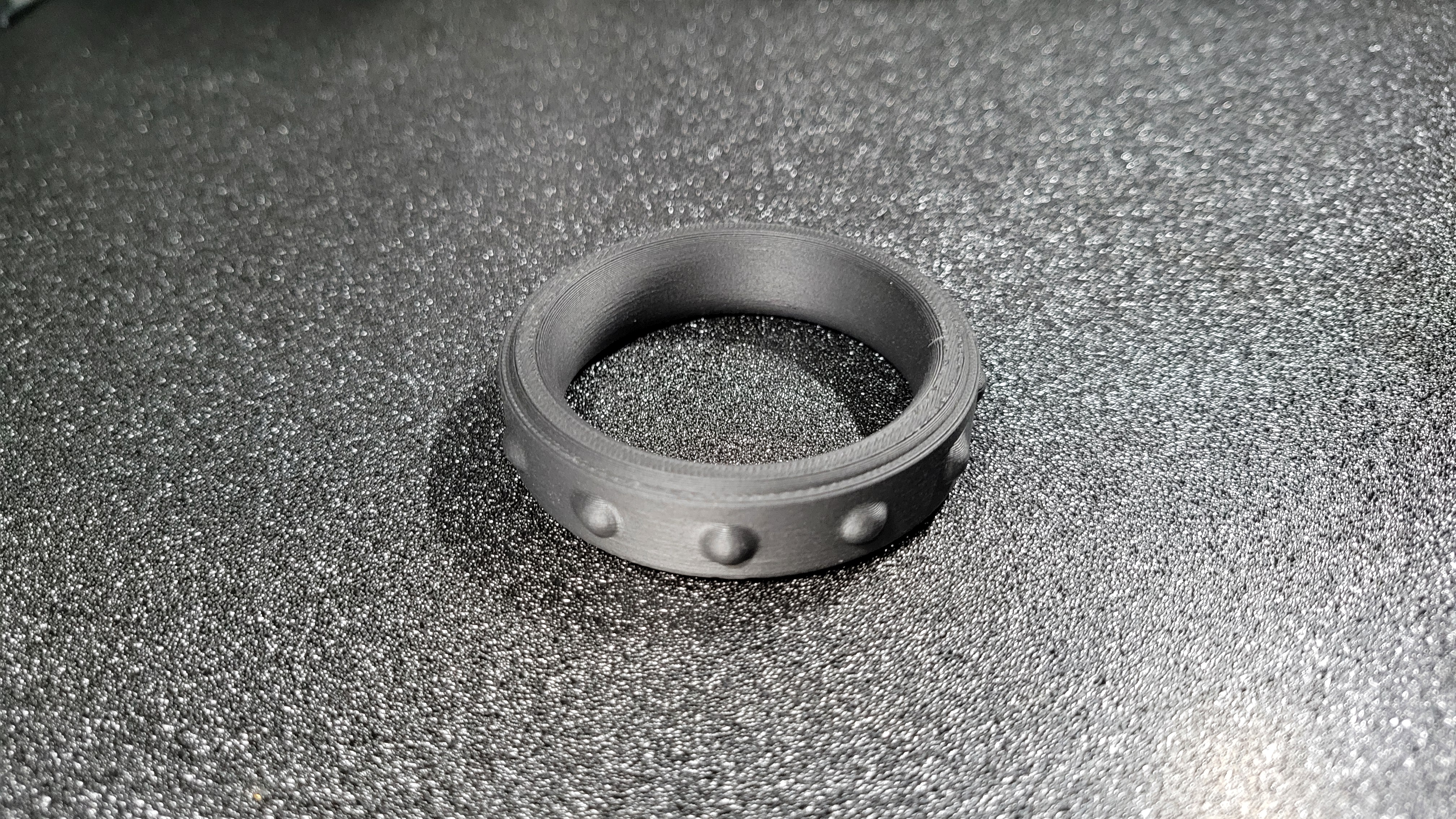
So now for the fun part. We have an .stl file so it’s time to turn our design into a physical piece of kit that we can actually use. I now load the file up in the slicer for my 3D printer and produce the ring itself. Nothing fancy is needed - I typically slice with very little infill and just use whatever color I have an abundance of. After some time, the physical ring is ready for testing. Depending on the design in question, some post processing before wear may make sense. Because a 3D printer doesn’t have perfect accuracy, sometimes there can be rough edges or layer lines that just plain don’t feel good. With the ring now ready, it’s time to put it on and run through all the usual checks to know if it works for you. Does it fit well? Does it feel good? Does it look how you like? Having completed this process several times for my designs, I usually only need to create one or two 3D printed prototypes before I feel confident in spending the money on turning it into something more permanent.
Production
We have a working design that hits all the marks - now it’s time to make it really real! Since I’m a huge fan of metal adornments, all of my custom designs get made as metal… but the question you’re faced with is who would make it and which metal would they make it in? I’ve browsed online CNC services several times and always come back to the folks at RapidDirect for a few reasons.
- Price: Consistently the lowest cost with the most common materials I use.
- Convenience: Their online app and automated DFM (Design for manufacturing) analysis is helpful for quick uploading and quoting.
- Quantity: They can produce one or a thousand of your custom parts
- Capabilities: Their equipment is able to handle cuts and designs that others have struggled with. They also offer electropolishing services on top of their base machining to give a nice, clean finish.
- Service: When the design cannot be manufactured, their sales and engineering staff help you understand why and what can be changed to make the design easier for the machinery.
For me, they tick all of the boxes I care most about - but feel free to do your research to find the best manufacturer for you.

For most designs, I go with 304 stainless or 6061 aluminum. The choice between the two boils down to preference since both are body safe materials. The 304 stainless is going to be heavier, but darker in finish while the 6061 aluminum will be extremely light and much “whiter” in color. I pretty much always pursue the electropolished finish, but brushed and sanded finishes are also available by most manufacturers. Just recently, RapidDirect started offering mirror polished electropolishing, which this blog entry will be the first to use! Above you can see a screen shot of the part just after I uploaded it. Within less than a day, I received confirmation that the design is suitable for their equipment and the quote was completed. All I had to do was pay and off it went.
The end result: 10 days after the order was placed, the design was shipped. About 7 days later, it was in my hands. The total cost for this 304 stainless steel adornment with a mirror polish was $120.40 US. Not bad at all given the cost of other non-custom rings!
While this specific design isn’t particularly intricate or elaborate, the process captured here in this blog entry should give you a rough idea of what to expect when creating your own custom adornment. As a maker, it is extremely rewarding to blend two of my hobbies to end up with such a fantastic result. If you’ve been thinking of taking the plunge, give it a shot!